
1.0 INTRODUCTION
A domestic water system describes the indoor and outdoor potable water distribution system. It includes the connection to the water supply, whether it is an underground central city, county, state or federal distribution system or a private well. The domestic water system includes above-ground and below-ground piping, valves, fittings, ancillary equipment and the various plumbing fixtures that use the potable water.
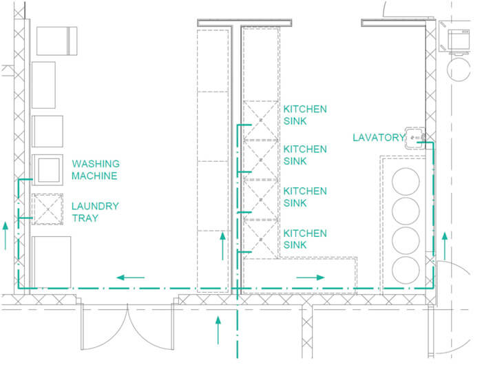
Figure 1: This figure shows an example of a domestic water distribution system (only cold water) for a commercial kitchen. This figure will be used to exemplify how a domestic water system is sized.
1.1 UNITS
The primary units that are used in this calculator and guide are the United States Customary System Units (USCS). However, there will be another version provided in International System of Units (SI). This version is not guaranteed and is not included with the purchase of this product.
2.0 DISCLAIMER
In no event will Engineering Pro Guides be liable for any incidental, indirect, consequential, punitive or special damages of any kind, or any other damages whatsoever, including, without limitation, those resulting from loss of profit, loss of contracts, loss of reputation, goodwill, data, information, income, anticipated savings or business relationships, whether or not Engineering Pro Guides has been advised of the possibility of such damage, arising out of or in connection with the use of this document/software or any referenced documents and/or websites.
This design guide book and calculator was created for the design of primarily commercial and residential domestic water systems. Although these products can be used for industrial type systems, the intricacies of industrial type plumbing fixtures make it very difficult and it is not recommended that you use this calculator industrial purposes.
3.0 PLUMBING CODES
The design of a plumbing system is greatly influenced by your applicable codes. The most common plumbing codes are the (1) International Plumbing Code or IPC, (2) Uniform Plumbing Code or UPC and (3) Unified Facilities Criteria Plumbing Systems or UFC 3-420-01 Plumbing Systems. Each plumbing design will follow under a certain jurisdiction, which is the governing power that makes the legal determinations and interpretations of the code. For example, a job may be on a federal base, which means the federal government has jurisdiction. This jurisdiction then determines that all plumbing designs must follow UFC 3-420-01 Plumbing Systems. If you do a job for a state government property, then that state has jurisdiction and you need to check with the jurisdiction for the applicable code. There are many different jurisdictions like federal, state, city and county. Each of these jurisdictions will tell you which code to follow, whether it is IPC, UPC or UFC and each of the jurisdictions may have adapted the code to fit their specific location’s needs.
This design guide will focus on the two most applicable codes, UPC and IPC. Just be sure to search through your jurisdiction for any adaptations.
3.1 APPLICABLE SYSTEMS
Plumbing systems include domestic water (cold and hot), sanitary sewer and vent, storm drain, special waste like grease and special systems (oxygen, fuel-gas, vacuum, nitrogen).
This design guide focuses on domestic water systems, primarily cold water. Hot water is not including in this design guide. This design guide focuses on the domestic water piping, plumbing fixtures, valves, booster pumps and other miscellaneous design issues related to the design of domestic cold water systems.
3.2 Water Supply Fixture Units
Prior to sizing a domestic water system and determining pipe sizes it is important to understand the concept of fixture units. Water Supply Fixture Units (WSFU) is the standard method for estimating the water demand for a building. This system assigns an arbitrary value called a WSFU to each fixture in a building, based on the amount of water required and the frequency of use.
For example, a water closet (tank) is assigned a WSFU of 2.2 fixture units (FU) while a sink (lavatory) is assigned 0.7 FU. These values are based on the International Plumbing Code Water Supply Fixture Unit table. The difference in fixture units is due to the fact that a toilet requires more water than a sink. The frequency of use between a private sink and a water closet would be the same, since a person will normally use the water closet and the sink within the same bathroom visit. A public water closet has a WSFU value of 5.0. Even though the water closet (tank) is the same as the private water closet and uses the same amount of water, a public water closet has a higher WSFU value. The public water closet has a higher usage frequency, which increases the WSFU value.
IPC: The international plumbing code or IPC uses the following water supply fixture unit table.
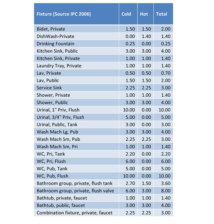
The water supply fixture units are distinguished between cold, hot or both. If a plumbing line serves only the cold water side of a fixture, then the corresponding value should be used. For example, a main line may serve the both cold and hot water, but then a branch line may go to the hot water heater. The branch line would only use the hot water value.
If a plumbing fixture is not available in the table below, then a fixture unit value can be assigned by the designer or engineer. Typically, a similar plumbing fixture that has a similar maximum flow rate and frequency of use will be selected. If the plumbing fixture will be on for long periods of time, then the volumetric flow rate can be inserted into the domestic water piping calculator.
4.0 DOMESTIC WATER PIPE SIZING
The sizing of domestic water supply system must be based on the minimum pressure available for the building in question. The designer must ensure that the required pressure is maintained at the most hydraulically remote fixture and that proper and adequate quantities of flow are maintained at all fixtures. In addition, the designer must ensure that reasonable velocities are maintained in all piping. The velocity of water flowing in a pipe should not exceed 10 feet/sec and should be designed for 7-8 feet per second or less, because high velocities will increase the rate of corrosion leading to pipe failure and cause undesirable noises in the system and increase the possibility of hydraulic shock. The designer should compute and/or know the following:
- Hydraulically remote fixture
- Available main pressure
- Pressure required at individual fixtures
- Static pressure losses (height of highest fixture relative to main pressure)
- Water demand (total system, and each branch, fixture)
- Pressure loss due to friction
- Velocity
Hydraulically Remote Fixture: The most remote fixture is the fixture that is the furthest distance away from the main domestic water supply point. The most hydraulically remote fixture is the fixture that is not necessarily the furthest away but the fixture that will have the least pressure given the projected water demand.
Available Main Pressure: The civil or fire protection engineer will typically investigate the main water pressure available at the project site. This pressure will determine the starting point for the pressure loss calculations. If there is insufficient pressure available to meet the pressure required at the individual fixtures, then a booster pump will be required. In addition, if the pressure is too high, then a pressure regulating valve will be required. High pressures at the plumbing fixture can lead to unsafe operation and unnecessary water loss.
Pressure at Individual Fixtures: The mechanical engineer should research the plumbing fixtures and determine the required pressure. For example, tank water closets only require 5 psig, while flush valve water closets can require 15 psig. Each plumbing fixture will have a different pressure requirement. Even different manufacturers of similar plumbing fixtures will have a different pressure requirement.
Static Pressure Losses: The static pressure losses are found by taking the difference between the initial elevation at the available main pressure point and the final elevation at the hydraulically remote fixture.
Friction Loss: The friction losses are determined by finding the flow rate, velocity, pipe size, pipe roughness for the entire hydraulically remote run. Friction losses can be due to the viscous forces of fluid flowing through the pipe and similar losses through fittings like elbows and tees. Lastly, friction losses are also due to miscellaneous equipment like water meters, valves, backflow preventers, pressure regulating valves, etc.
Water Demand: The water demand is the projected flow rate. The projected flow rate is based on the water supply fixture units and any other continuously operated fixtures. The water demand is important because as the water demand increases, there will be an increase in friction losses. This will reduce the pressure at the hydraulically remote fixture. Thus, the water demand must be checked along with the pressure at the hydraulically remote fixture.
Velocity: Based on the water demand, the projected velocity can also be found. The velocity within the piping must be limited in order to avoid excessive noise, water hammer and increased pipe erosion.
4.1 MAIN AND BRANCH PIPING SIZING
It is very difficult to quickly obtain the velocity, water demand, friction loss and static pressure losses within a piping system, just to size the plumbing lines. Often times, estimates are used to size the main and branch piping, which can lead to inaccuracies and increased pressure losses or oversized piping. These estimates typically consists of a table of copper pipe sizes and the maximum fixture units that each pipe size can serve. The designer will sum the WSFUs that are served by each pipe and then choose a pipe size that can accommodate the total WSFUs.
This process is exactly the same as the previous process, with a table and the maximum WSFUs for each pipe size. Except, the table can be customized for any pipe material, tank or flush valve and for any range of velocities and pressure drops. The previous process determined the maximum WSFUs for a pipe size based on some random velocity limitation and/or pressure loss limitation. However, higher velocities can be accommodated in certain areas where water hammer and noise are not an issue. Higher pressure drops can also be accommodated on piping that is not part of the hydraulically remote run.
In both processes, the piping layout must be completed. The piping layout consists of the geometrical arrangement of the pipes from the water supply to all plumbing fixtures.
4.1.1 STEP 1: DETERMINE WSFU
The water supply fixtures units (WSFU) fed by a pipe is determined by the number of each plumbing fixture that is connected to the pipe and the governing plumbing code. The plumbing code establishes the WSFU value for each fixture type. The piping layout determines the amount of each fixture type that is fed by each pipe.
4.1.2 STEP 2: CONVERT WSFU TO GPM
The next step is to convert the WSFU value to gallons per minute (GPM). This volumetric flow rate will help to determine the pressure drop and fluid velocity within the pipe in the next and final step. The conversion from WSFU to GPM will depend on whether or not the connected fixtures are predominantly flush valve type or tank type.
Flush Valve vs. Tank: This distinction is common of toilets. A tank type toilet uses the tank fluid elevation to forcefully flush the toilet waste through the waste system. After a tank toilet is flushed, a fill line is used to fill up the tank. The fill time is typically around 20 seconds. At a residence or where there is infrequent use, this fill time is acceptable. However, in a public space with frequent use, this fill time is not acceptable. A flush valve toilet is used in these situations. A flush valve type toilet does not have a tank to provide the pressure to force the waste into the waste system. Thus, a flush valve toilet will require a much higher minimum pressure.
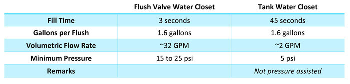
Table 1: This table shows that tank type water closets require less pressure and a lower flow rate than flush valve type water closets.
A pipe that feeds predominantly flush valve type fixtures will have a greater volumetric flow rate requirement than a pipe that feeds predominantly tank type fixtures.
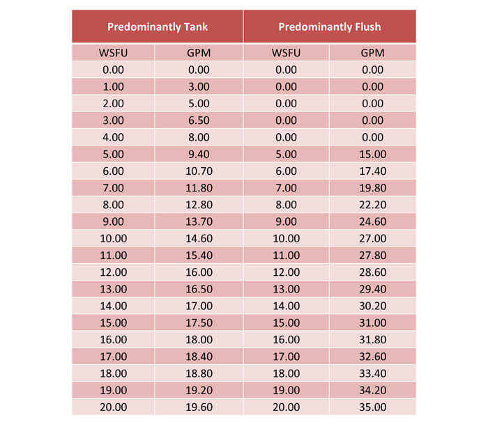
Table 2: This table shows the WSFU to GPM conversion difference between a predominantly tank type versus a predominantly flush valve type.
Predominantly Flush vs. Tank Type: A group of plumbing fixtures is considered predominantly flush valve if the group has more than one flush valve for every ten tank type water closets. Other companies may use a different determination, but the reasoning is that one flush valve type water closet has a significant impact to the maximum flow rate for a pipe, as shown by the table that showed the fill velocity as 32 GPM versus 2 GPM. If there is a branch run that serves no flush valve type water closets, then that branch can use the predominantly tank type WSFU to GPM conversion. But all pipes downstream from a predominantly flush valve type branch will need to be sized with the same conversion, unless the amount of tank type water closets becomes much greater than the amount of flush valve type water closets.
4.1.3 STEP 3: QUICK SIZING TABLE
Once the WSFU and the appropriate GPM conversion are determined, then the quick sizing table can be used to select the appropriate pipe size. The first step in using this table is to select the pipe material, pipe sub-type, predominantly tank/valve and the C-value. The pipe materials, C-values and sub-types are discussed in a subsequent section in this guide. The tank vs. flush valve type has been discussed earlier in this section. The C-factor describes the pipe smoothness. Steel pipes are given a C-factor of 100 and smoother pipes have a higher C-factor and rougher pipes have a lower value. For example, copper’s C-factor is typically 135 to 150, CPVC & PVC is 150.

Figure 2: The first step in using the custom quick sizing tables is to select the pipe material, sub-type, valve or tank and the C-value.
Once the pipe information has been entered, then the next step is to determine what are the acceptable velocities and pressure drops within the pipes. This will vary between each situation and each company. Each company will have its own standards, but below is a brief discussion on the typical acceptable velocities and pressure drops.
Sizing Based on Velocity: The typical ideal pipe fluid velocities for a domestic water system are between 4 and 8 feet per second (fps). Less ideal velocities are between 2 and 4 fps and 8 to 10 fps. At higher velocities, 6 to 10 fps, there will be increased erosion over time and noise during operation. At the lower velocities 2 to 6 fps, erosion and noise will not be a concern, but there may be a stagnation concern and there will be an inefficient use of money.
Velocity Pressure: The pressure drop through fittings is dependent on the velocity pressure, which is dependent on the fluid velocity. At higher velocities, the pressure drop through a fitting will be significant and may lead to insufficient pressure at the fixtures. The equation used to solve for velocity pressure is shown below.

The pressure drop through fittings is found by multiplying the velocity pressure by a K-factor that is used to characterize the fitting geometry, fitting size and turbulence within the fitting. A typical fitting is a 90 degree long radius elbow with a K-factor of 0.24. The table below shows the pressure loss of ten 90-degree elbows at varying velocities.
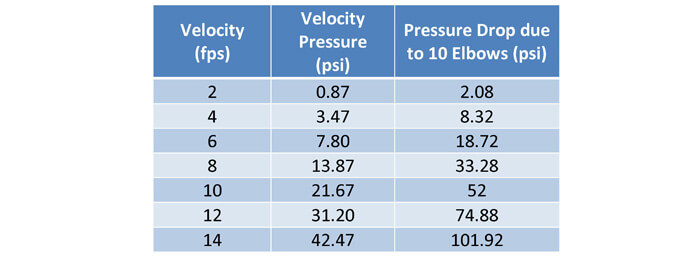
Figure 3: A greater velocity will cause increased pressure drop through fittings.
A lower velocity is more suitable for pipe runs with a lot of fittings. If there is sufficient pressure, then a higher velocity can be accommodated.
Sizing Based on Pressure Drop: The second method used to size pipes is through an acceptable pressure drop per 100 feet. The typical values range from 1.7 to 3.4 psi per 100 feet of piping or 4 to 8 feet of head per 100 feet of piping. Less ideal values range from 1 to 1.7 and 3.4 to 4 psi per 100 feet of piping. The lower pressure drop range is less ideal because it means the piping is oversized. The upper range is less ideal, because it may lead to insufficient pressure at the plumbing fixtures.
The pressure drop is determined through the Hazen-Williams equation. This equation is shown below. This equation is not accurate for laminar flow and for extremely turbulent flow. However, this equation is very useful for the typical velocities of 2 to 10 fps and higher velocities.
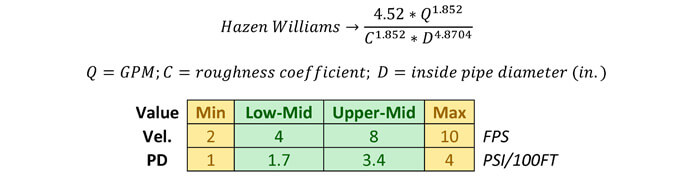
Figure 4: The second step is to determine the acceptable pipe sizing criteria. Pipes can be sized based on pressure drop, velocity or both. This part of the calculator allows you to pick your preferred range in green and your acceptable range on the high side and low side in yellow.
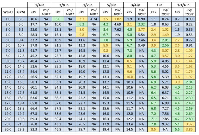
Figure 5: This figure shows a snippet of the quick sizing table based on the previous inputs. The green indicates a velocity or pressure loss value within the ideal range. Yellow indicates a value within the acceptable but not ideal range.
The pressure drop values are not as accurate for the lower and higher velocities. This is because the quick sizing calculator uses the Hazen Williams equation as opposed to the Darcy Weisbach equation.
4.2 FIXTURE PIPING SIZING
The pipes that directly feed the fixtures are sized based on the table below. These pipes are the rough-in pipes that connect to the branch pipes. Do not get this pipe confused with the fixture connection pipe. The fixture manufacturer will indicate the fixture connection sizes, but these sizes typically refer to the braided hose sizes and not the rough-in pipes. A rough-in pipe will typically be copper, which will be soldered to a dielectric union. On the other end of the dielectric union will be a threaded metal fitting. A shut off valve can be connected to this metal fitting, followed by a braided hose. The braided hose is then connected to the fixture piping connection. The size of the braided hose is determined by the fixture manufacturer.
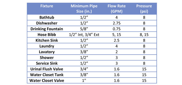
Table 3: This table shows the rough-in, pipe size for various plumbing fixtures.
4.3 SAMPLE PIPE SIZING DISCUSSION
Now, you can use the quick sizing table to go through the piping layout and assign sizes to each pipe segment based on the connected WSFU values. The next part of this guide will take you through a sample layout, based on Copper Type K tubing. The sample layout is shown on the following page, but the discussion starts below.
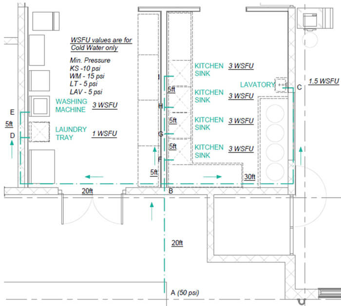
Figure 6: This figure shows a sample cold water distribution system, with each plumbing fixture labeled with its IPC WSFU values for cold water only. In addition, the flow direction is shown and the lengths of each pipe segment. Finally, the initial point, “A” shows a starting pressure of 50 psi and the minimum required pressure values are also shown.
Size B-C Segment (1.5 WSFU = 1/2”): The first segment that will be sized will be segment B-C, which only serves a lavatory. Since this line only serves a single fixture then you can use the fixture table, which indicates that the minimum pipe size as 3/8”. However, the pipe length is fairly long and according to the quick sizing table, there will be a large pressure drop. So a 1/2” pipe should be used for the long run. The individual connection to the fixture will be 3/8”.
Size E-D Segment (3 WSFU = 3/4”): The next segment that will be sized will be segment E-D, which only serves a washing machine. At 3 WSFU, the quick sizing table will need a 3/4” pipe. If you also check commercial washing machine product data, you will also find that the typical connection size is 3/4” for both cold and hot water.
Size H-I Segment (3 WSFU = 3/4”): The next segment that will be sized will be segment H-I, which only serves a kitchen sink. At 3 WSFU, the quick sizing table will need a 3/4” pipe. If you also check commercial kitchen sink product data, you will also find that the typical connection size is 1/2” for both cold and hot water. For the individual fixture piping, you should use a 1/2” pipe but for the H-I, you should use a 3/4” pipe.
Size G-H Segment (6 WSFU = 1”): This segment serves two kitchen sinks, which totals to 6 WSFU. The quick sizing table indicates that this pipe should be 1”.
Size F-G Segment (9 WSFU = 1-1/4”): This segment serves three kitchen sinks, which totals to 9 WSFU. The quick sizing table indicates a pipe size of 1-1/4”.
Size B-F Segment (12 WSFU = 1-1/4”): This segment serves four kitchen sinks, which totals to 12 WSFU. The quick sizing table indicates a pipe size of 1-1/4”.
Size B-D Segment (4 WSFU = 1”): This segment serves one washing machine and one laundry tray, which totals to 4 WSFU. The pipe size should be 1”.
Size A-B Segment (17.5 WSFU = 1-1/4”): This segment serves four kitchen sinks, one lavatory, one washing machine and one laundry tray, which totals to 17.5 WSFU. The quick sizing table indicates a 1-1/4” pipe.
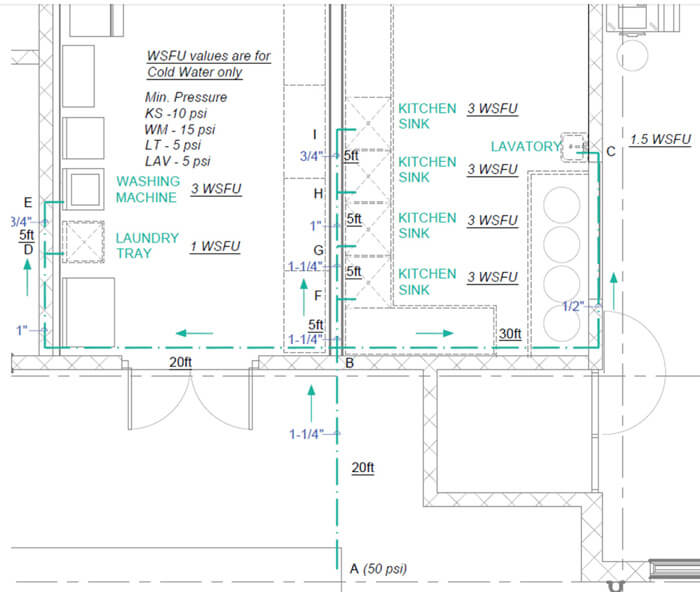
Figure 7: This figure shows the results of the pipe sizing example. The pipe sizes are determined based on the quick sizing table for Type K Copper Tubing.
5.0 Domestic Water Pressure Calculator
Once the designer has completed the first pass of the pipe routing and sizing, the designer can use the excel file, Domestic Water Calculations.xls in order to determine the pressure loss of the piping, fittings and miscellaneous equipment. This will determine if there is sufficient pressure at the most hydraulically remote fixture. If there is not sufficient pressure, then a domestic water booster pump will be required.
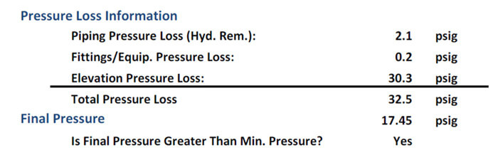
Figure 8: The calculator will automatically output the above results. This shows the pressure loss due to piping, fittings, miscellaneous equipment, valves and elevation change. Then the calculator compares the final pressure at the hydraulically remote fixture to the required minimum pressure at the hydraulically remote fixture.
The first step in using the domestic water pressure calculator sheet is to input the basic water information shown below.
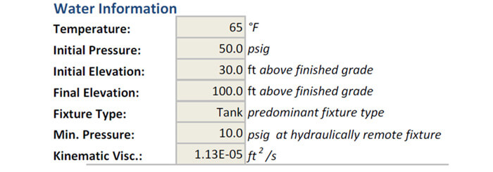
Figure 9: The water information is the first set of inputs required for an output from the domestic water piping pressure calculator. The temperature determines the kinematic viscosity. The initial pressure is typically provided by a civil engineer, fire protection designer or by a city/county/state/federal utility provider. The initial and final elevation is shown in feet above finished grade. The difference between these two values determines the static pressure loss. The fixture type is used to determine the WSFU to GPM conversion. The minimum pressure is the lowest pressure required at the hydraulically remote fixture.
The second step is to insert the piping information.
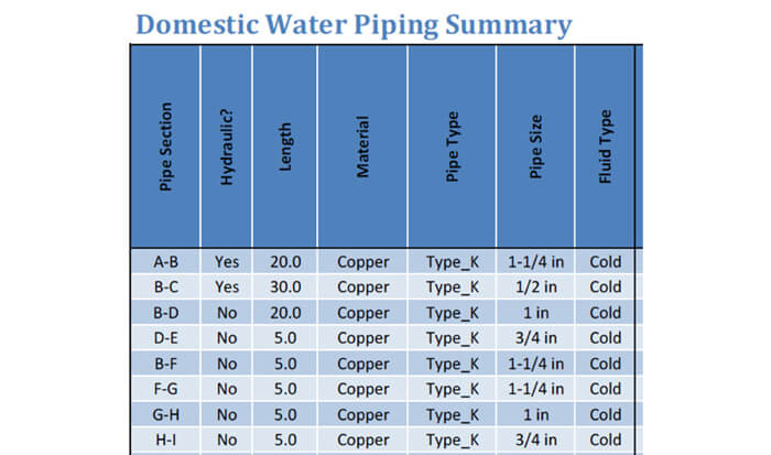
Figure 10: The second step involves inserting the basic piping information for each pipe section. A pipe section changes whenever the pipe size/material or the fixtures served by the pipe changes.
The third step is to add the fixtures that are served by each piping section.
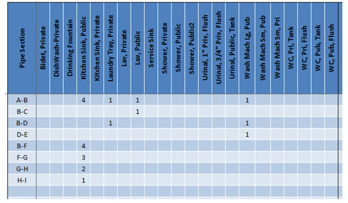
Figure 11: The fixtures served by the pipe determine the WSFU value, which then determines the flow rate within the pipe section.
The fourth step is to check the velocities and piping pressure losses. If the velocities or pressures are not acceptable, then you may need to adjust the pipe size.
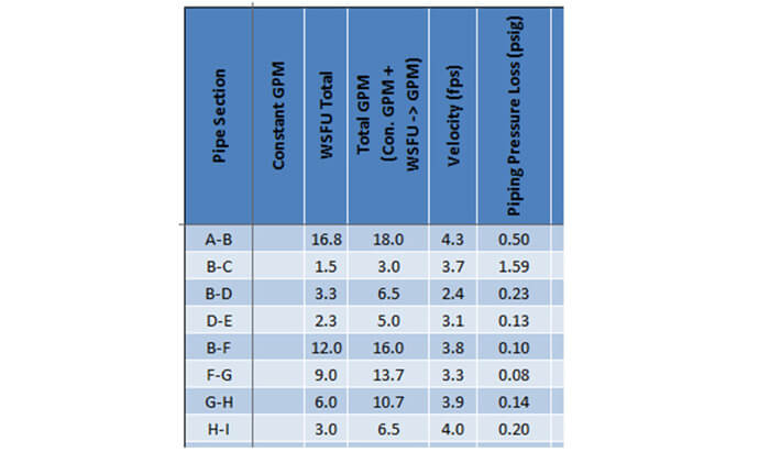
Figure 12: Check the velocity and pressure drop for anything out of the acceptable or ideal ranges.
The valves and fittings section requires you to put in the values for each fitting that are on a certain pipe section. A pipe section is defined as having the same flow rate and same pipe information.
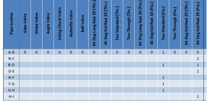
Figure 13: These are the possible fittings that are built-into the calculator. If your fitting is not present, then look for a similar fitting and adjust the K-values for the fitting as shown in the following sections.
The next step is to insert the pressure loss for any miscellaneous equipment like a water meter or backflow preventer.
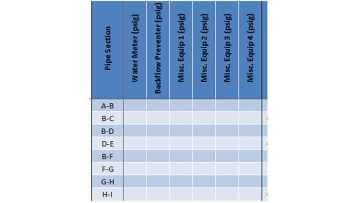
Figure 14: The pressure loss due to equipment is specific to the manufacturer of the equipment. You should check the manufacturer product data for this information, but you should also remember that the pressure loss is specific to a certain flow rate. If your flow rate is different, then you will need to adjust the pressure drop to match your application.
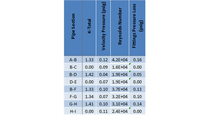
Figure 15: The calculator automatically determines the K-total from all the fittings, the velocity pressure, Reynolds number and the pressure loss due to the fittings/valves.
Following all of the previous steps, the calculator with then determine whether or not you need a booster pump and will also determine the available pressure at the hydraulically remote fixture.
The following sections will discuss in more details the equations used to determine the following items within the calculator: Fluid Velocity, Reynolds Number, Friction Factor and Pressure Drop due to Piping, Fitting, Valves and Equipment.
5.1 FLUID VELOCITY
The first equation uses the inputs from the pipe information section and the user input flow rate to find the fluid velocity in the pipe. When you choose the pipe material, pipe type and pipe size, the calculator will automatically determine the inner area from the table within the references. If the combination of pipe material, pipe type and pipe size is not in the calculator then a “N/A” will appear in the velocity column. You should double check to make sure the combination exists before proceeding.

5.2 REYNOLDS NUMBER
The next equation calculates the Reynolds Number. This equation uses the velocity from the previous equation along with the pipe inner diameter and the fluid properties (density & viscosity).

The Reynolds Number classifies the fluid flow into either (1) Laminar, (2) Transition or (3) Turbulent. The breakdown between these three classifications is defined below. The friction calculations are most accurate with fluid flow in the turbulent region. For this reason, the calculator will highlight in red any Reynolds Number that is below the turbulent region.

5.3 FRICTION FACTOR
The friction factor is found through the Colebrook Equation. The Colebrook Equation relates the friction factor to the Reynolds Number and the relative roughness.

Iterative Process: Since the friction coefficient is on both sides of the equation, you must use an iterative process to find the friction coefficient. You must first choose a value for the friction coefficient on the right side of the equation and then solve for the friction coefficient on the left side. Then use the friction coefficient that you just computed and plug-in this value to the right side of the equation and repeat the process. The process ends when the right and left side friction coefficients converge to nearly the same number. The calculator completes this process by running nine iterations.
Turbulent Flow: This equation only works for turbulent flow. A different equation is used for laminar flow. Luckily in practical chilled water applications, flow is nearly always turbulent. However, the calculator does incorporate conditional formatting to visually tell you if the flow is not turbulent. You should use your knowledge of the turbulent range from the previous section to ensure that your flow calculations are in the turbulent range.
5.4 PRESSURE DROP – PIPING & VALVES/FITTINGS
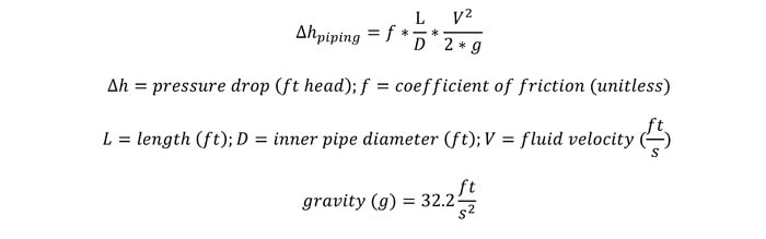
The pressure drop for a straight length of piping is found through the friction factor and the Darcy Weisbach equation. This equation uses the velocity, friction factor, pipe inner diameter and the length of piping to calculate the pressure drop. For more details, see the equation below. The output for this equation is the pressure drop in units of feet head.
The pressure drop through valves and fittings is found through the 3-K method. The 3-K method uses three K-values to characterize each type of valve and fitting. These three K-values are K1, Kinf and Kd. These K-values are used with the Reynolds Number and nominal pipe diameter to find the final K-value.

Since, the calculated K-value is a function of Reynolds Number and nominal pipe diameter, the K-value is applicable for various pipe sizes, pipe materials, fluids and fluid velocities. Once you have the K-value, the K-value is used to calculate the pressure drop through the valves and fittings.

5.5 PRESSURE DROP – EQUIPMENT
There are no equations governing the pressure drop in equipment section. In this section of the calculator you can input the values for pressure drop at equipment. Typical equipment includes strainers, filters, flow meters, control valves and backflow-preventers. The pressure drop through this equipment at a specified flow rate must be provided by the manufacturer of the equipment. Typically, the manufacturer will provide a single value that indicates the pressure drop at a specified flow rate (GPM). Other times, a manufacturer will provide a graph that shows the pressure drop at various flow rates. This is typical of flow meters, control valves and strainers.
5.6 JOINING METHOD
In the fittings and valves section, you must choose the joining method. The available joining methods are flanged and threaded. Threaded fittings are the same as soldered, brazed and pressed fittings, for fluid dynamics purposes and for the calculator. Most often in the domestic water systems, you will use the flanged fittings. Threaded fittings are not often used for domestic water systems.
5.6.1 SOLDERING
Soldering is the primary method used to join copper for a building’s domestic water system. The American Welding Society defines soldering as “a group of joining processes that produce coalescence of materials by heating them to a soldering temperature and by using a filler metal (solder) having a liquidous not exceeding 840 F and below the solidus of the base metals.”
Soldering is different from brazing because it uses a lower temperature for the melting of the filler metal. It is different from welding because welding requires the two metals that are being joined to be melted.
The soldering process is fairly long when compared to the Propress system, shown below. Both processes involve proper measuring and cutting of the pipe. Once the pipe is cut it must be reamed, in order to provide a smooth surface for better flow. The pipe must then be cleaned, because the removal of all oxides and surface soil is necessary for the solder to properly flow onto the joint. A flux is a substance that will dissolve and remove traces of oxide from the pipe. Thus prior to assembling the two copper tube into the fitting the fitting and tube must be fluxed. Once this is complete and the tube and fitting are situated correctly, then the joint area can be heated and the solder can be applied.
5.6.2 BRAZING
Brazing is the joining of two materials using a third dissimilar material. This differs from soldering because it uses a higher temperature for melting the filler material. The brazing process is fairly similar to the soldering process. However, brazing occurs in the range between 1200 and 1550 F while soldering occurs below 840 F. Brazing is required when routing piping in the slab, according to UPC soldered joints on copper lines run under a slab are restricted. When running copper under a slab, wrought copper fittings are required and all joints must be brazed.
5.6.3 PRESS CONNECTION (PROPRESS)
This is the newest method of joining copper tubing, it was unveiled in 1999. It is more than on its way to becoming the favored joining method by many contractors because of the ease of installation. This system involves pre-engineered copper fittings, ranging from sizes from ½” to 4”.
6.0 PIPE MATERIALS
The most common inside building water distribution piping is copper. But this guide will cover other materials and their uses, properties, advantages and disadvantages.
There are other pipes available for use in the calculator but you can also add your own pipe information. The pipes built-in to the calculator include ASTM A53 Steel (Schedule 40 & 80), ASTM B88 Copper (Type K, L & M), ASTM D2241 PVC (SDR 26), ASTM F2389 Polypropylene (DR 9), ABS ASTM D1527, ABS ASTM D 2282, Brass Regular and Extra, CPVC ASTM F441 and F442, PEX, Ductile Iron, Galvanized Steel and Stainless Steel 304 & 316. These are the most common pipes used in chilled water pipe application. If you have a special case, then please use the references sheet to add in your pipe information or contact Justin via email contact@engproguides.com.
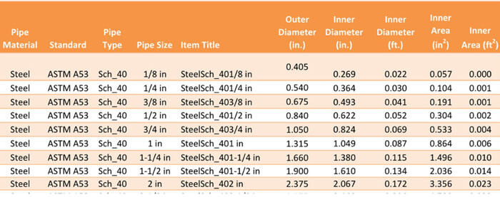
Figure 16: This figure is a sample of the pipe information built-in to the calculator, references tab.
Each pipe material and pipe type within that pipe material have its own standard pipe sizes. For example, Schedule 40 Steel does not have a 5/8 inch pipe size. When you change pipe materials and pipe types, please also change the pipe size to ensure the pipe size you want is available within the standard. The calculator will give you an error if you select a non-standard pipe size within the pipe material & type.
6.1 ABS PIPING
ABS stands for Acrylonitrile-Butadiene-Styrene. This piping is most often used for drainage, waste and vent systems and not used for domestic water systems. You can often see this pipe serving the waste for plumbing systems and it is often black. This piping is light and somewhat flexible and suitable for temperatures between -30 °F to 140 °F. Just like other plastic piping, ABS is not suitable for outdoor conditions when exposed to sunlight. The UV rays will degrade the ABS piping.
There are two standards that govern ABS piping, (1) ASTM D 1527 and ASTM D 2282. ASTM D 1527 is titled Standard Specification for Acrylonitrile-Butadiene-Styrene (ABS) Plastic Pipe, Schedules 40 and 80. ASTM D 2282 is titled Acrylonitrile-Butadiene-Styrene (ABS) Plastic Pipe, SDR-PR. These two standards give the dimensions and tolerances for the various ABS pipe types.
6.1.1 ASTM D 1527 SCHEDULE 40 & SCHEDULE 80
The pipe schedule describes the thickness and pressure rating for each pipe size. Schedule 80 has thicker walls than schedule 40 and thus schedule 80 piping has a higher pressure rating than schedule 40 piping. Schedule 40 and Schedule 80 piping have the same outside diameter, but their thicknesses are different. The schedule 80 piping has a greater thickness, which makes the inside diameter smaller when compared to schedule 40 piping.
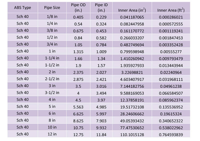
Table 4: This table shows the pipe dimensions for schedule 40 ABS plastic piping in accordance with ASTM D 1527.
Pipes will typically have the same outer diameter, because this allows pipes of different schedules to be joined together. As you can see, schedule 80 piping has the same outer diameter as schedule 40 piping for each specific pipe size. However, the inner diameter is smaller because the schedule 80 pipe has thicker walls.
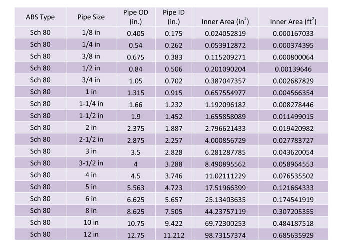
Table 5: This table shows the pipe dimensions for schedule 80 ABS plastic piping in accordance with ASTM D 1527.
6.1.2 ASTM D 2282 STANDARD DIMENSION RATIO (SDR)
The Standard Dimension Ratio or SDR describes the relationship between the pipe outer diameter and the thickness of the pipe wall.
For example, SDR 17 for an outside diameter of 1.315 inches will have a pipe thickness of 0.077 inches and 0.063 inches for SDR 21.
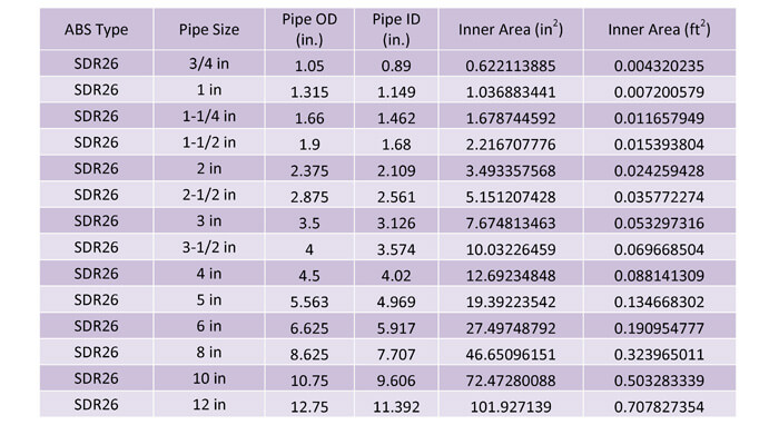
Table 6: ABS pipe type SDR 26 pipe sizes
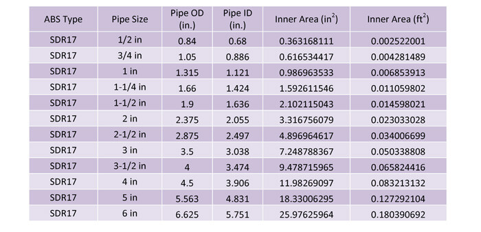
Table 7: ABS SDR 14 pipe sizes
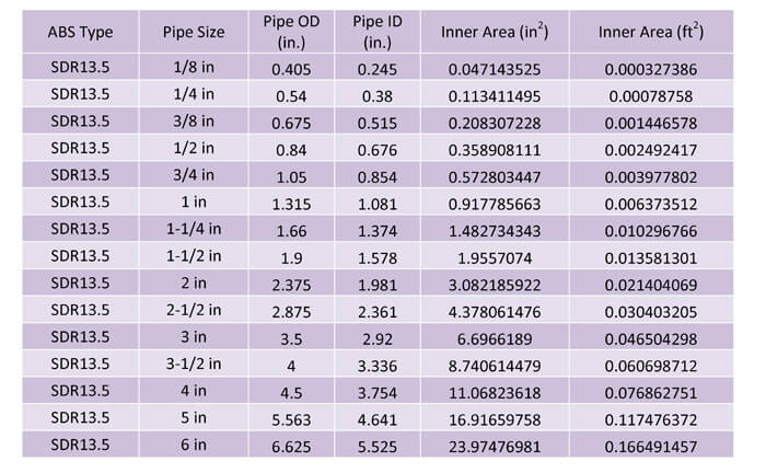
Table 8: ABS SDR 13.5 pipe sizes
6.1.3 PRESSURE RATINGS
The pressure ratings for ABS piping are determined by the pipe diameter, pipe thickness and the pipe material. Although the pipe material is ABS, there are different classes within the overall ABS pipe material family. The typical ABS pipe classes include ABS2112, ABS1316, ABS1210 and ABS1208. ABS 2112 is the strongest, then ABS1316, followed by ABS1210 and finally ABS1208. The burst pressure for these materials and SDR combinations are shown below.
6.2 BRASS PIPING
Brass piping is in some cases an approved potable water piping and was popular in the past, but it has been replaced by materials that are easier to work with and usually provide longer service. There are two types of brass piping, (1) regular strength and (2) extra strength. The extra strength brass has thicker walls, which allows this pipe to have a higher allowable working pressure. The table below shows the dimensions of brass regular and extra strength piping. As you can see the inner diameter for extra strength piping is slightly less than the equivalent regular strength pipe size. This is due to the increased pipe thickness.
6.2.1 REGULAR STRENGTH
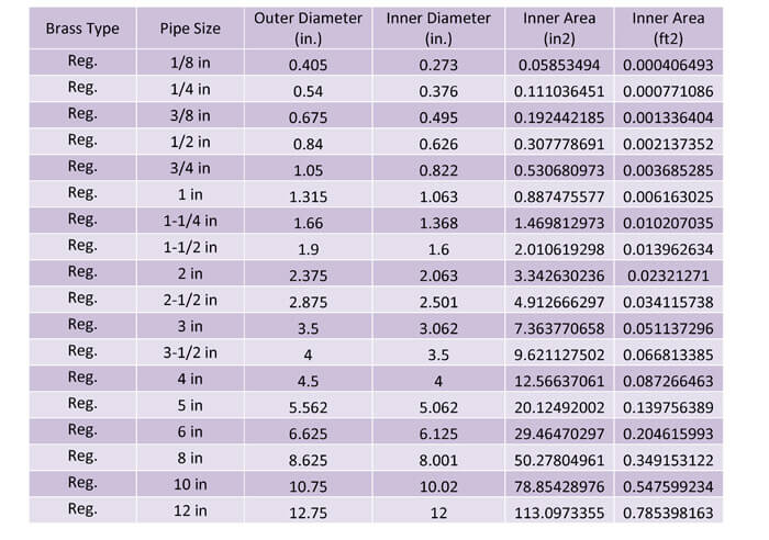
Table 9: This table shows the dimensions of regular strength brass piping.
6.2.2 EXTRA STRENGTH
Extra strength piping is typically not used for domestic water systems, since the pressures in domestic water systems typically never exceed 300 psi and the regular strength brass piping has sufficient strength to withstand 300 psi. The following two tables show the maximum allowable pressure for both regular and extra strength piping to further explain this point. As you can see, the maximum allowable pressure decreases with an increase in temperature.
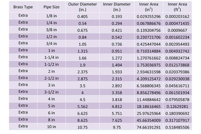
Table 10: This table shows the dimensions of extra strength brass piping.
6.2.3 PRESSURE RATINGS
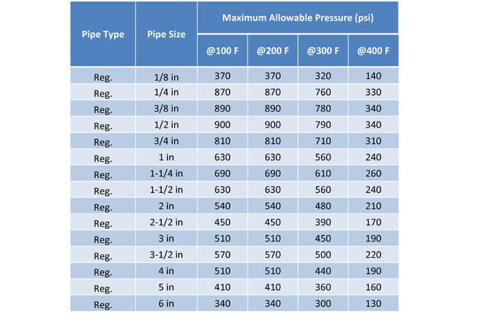
Table 11: The maximum allowable pressure decreases as the temperature of the fluid increases.
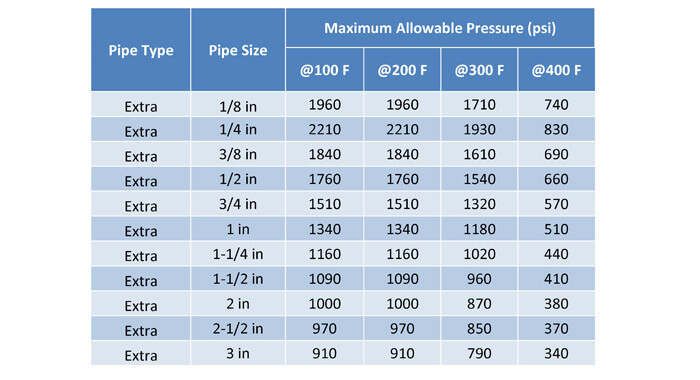
Table 12: The extra strength brass piping has much higher maximum allowable pressures as shown in the below table.
6.3 CPVC PIPING
Chlorinates Polyvinyl Chloride (CPVC) is a plastic piping that is used to distribute cold water and sewer, waste, vent systems. Its main benefit is that it is low cost and easy to install. It is suitable for pressurized cold water (73 F) at pressures up to 300 PSI for smaller diameters and thicker pipes. However, at higher temperatures (180 F) the pressure rating drops down to 100 PSI and lowers for thinner pipes and larger diameters.
CPVC is slightly stronger than PVC and can handle higher temperatures. However, CPVC cannot handle temperatures as high as copper piping. In addition, CPVC has a larger coefficient of thermal expansion than metal piping. This means that you will need to account for pipe expansions and reductions for long runs of CPVC piping.
There are two standards that govern the dimensions of CPVC piping. These standards are ASTM F441 and ASTM F442. The first standard provides dimensions in the Schedule format and the second standard in the SDR format.
6.3.1 ASTM F441 STANDARD SPECIFICATION FOR CHLORINATED POLY VINYL CHLORIDE (CPVC) PLASTIC PIPE, SCHEDULES 40 AND 80
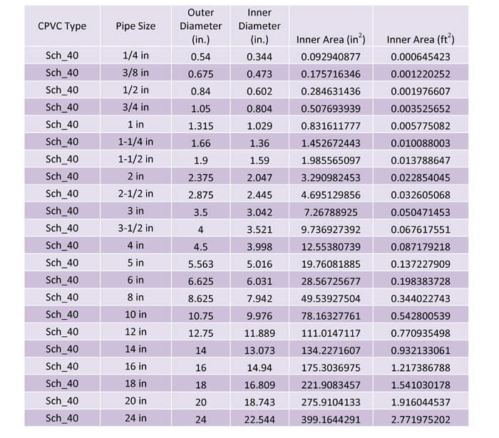
Table 13: This table shows the dimensions for CPVC Schedule 40 piping.
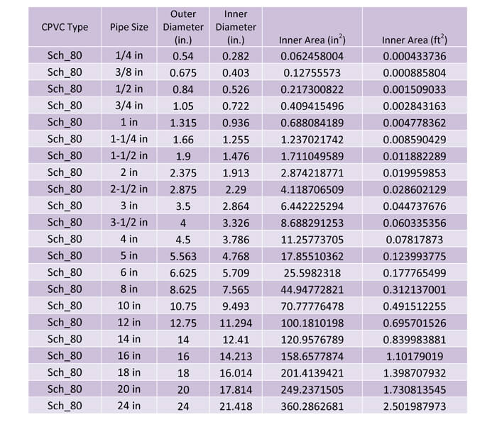
Table 14: This table shows the dimensions for CPVC Schedule 80 piping.
The pressure rating of the piping ranges from 1,130 PSI for Schedule 80, 1/4” pipe down to 230 PSI for Schedule 80 12” pipe and 210 PSI for Schedule 80 24” piping. The pressure rating also ranges from 780 PSI for Schedule 80 ¼” piping down to 220 PSI for 4” Schedule 40 piping and even further down to 120 PSI for 24” Schedule 40 piping. As you can see the pressure rating (maximum allowable water pressure) decreases as the size of the piping is increased and the pressure rating for schedule 80 piping is higher than the pressure rating for Schedule 40 piping.
The pressure rating is also de-rated as the water temperature increases. The previous pressures are based on 73 F water temperature. The pressure rating is de-rated down to 20% of the pressure rating when the water temperature is 200 F. The pressure ratings for piping are readily available from pipe manufacturer’s websites. But as a designer you should understand that CPVC is not suitable for high temperature water at pressures greater than 100 PSI and even lower for larger pipe sizes.
6.3.2 ASTM F442 STANDARD SPECIFICATION FOR CHLORINATED POLY VINYL CHLORIDE (CPVC) PLASTIC PIPE, SDR-PR
Similar to ABS piping, CPVC can also be rated in the SDR format. However, most manufacturers in the United States do not use this format. Thus these pipe sizes are not included in this guide nor are these pipe sizes included in the calculator.
6.4 COPPER PIPING AND TUBING
6.4.1 DIFFERENCE BETWEEN PIPING AND TUBING
Piping is primarily used as a fluid carrier and is measured by inside diameter (ID). Thus when a ½” nominal copper pipe is selected, the inside diameter is roughly ½” while the outside diameter is 0.625 inches. Tubing is primarily used for structural purposes and is measured by outer diameter (OD). A ½” copper tube has an outer diameter of 0.545 while its ID is less than ½”. In domestic water piping systems, copper tubes are used and not copper pipes.
6.4.2 COPPER TYPES
There are six standard types of copper and are shown below for reference, you should select the type that most closely matches your project’s situation:
6.4.3 TYPE K COPPER TUBING
Type K copper tubing is commercially available in 20 ft lengths, drawn or annealed. It can be used for domestic water, fire protection, fuel, fuel oil, refrigerants, compressed air, LP gas and vacuum. It has the thickest walls of types L and M. Type L walls are thicker than Type M. These relations hold true for all pipe diameters. The outside diameters for each type, only the inside diameters and wall thicknesses vary for each type.
This type of pipe is most often used for below ground installations or when damage can occur to an above ground installation and a harder material is required.
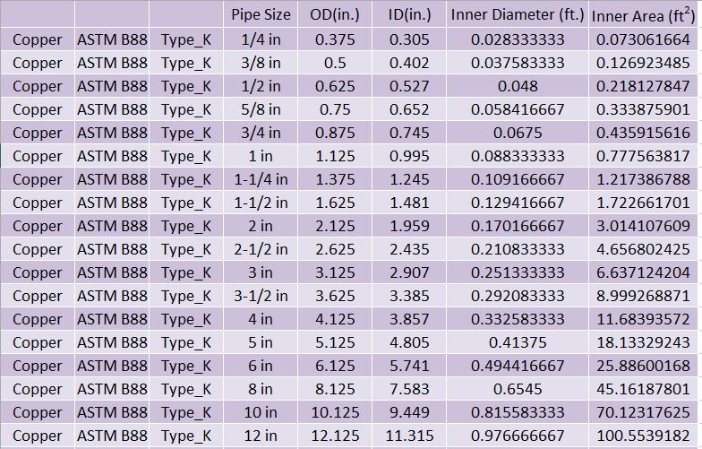
Table 15: Type K Copper Tubing Table
6.4.4 TYPE L COPPER TUBING
Type L copper tubing is commercially available in 20 ft lengths, drawn or annealed. It can be used for domestic water, fire protection, fuel, fuel oil, refrigerants, compressed air, LP gas and vacuum. It has the second thickest walls of Types K, L and M.
This type of pipe is most often used for above ground installations and when possible damage is not likely to the above ground installation.
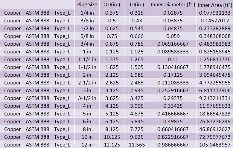
Table 16: Type L Copper Tubing Table
6.4.5 TYPE M COPPER TUBING
Type M copper tubing is commercially available in 20 ft lengths, drawn or annealed. It can be used for domestic water, fire protection, fuel, fuel oil, refrigerants, compressed air, LP gas and vacuum. It has the thinnest walls of Types K, L and M.
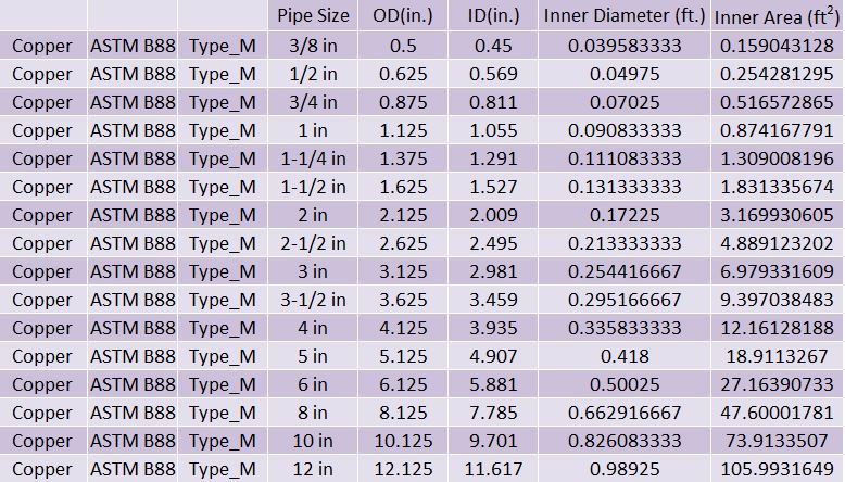
Table 17: This table shows the pipe dimensions for Copper Type M tubing.
6.4.6 TYPE DWV COPPER TUBING
Type DWV: This type has the thinnest walls and is used in drain, waste, vent applications where little to no pressure is involved. This type should not be used for pressurized water, so it is not included in the Domestic Water Piping Calculator.
6.4.7 TYPE MEDICAL GAS COPPER TUBING
Type Medical Gas: This type has an internal cleanliness requirement that meets the standards for piping conveying oxygen, nitrogen, nitrous oxide, medical compressed air or other gases used in medical facilities. This type should not be used for pressurized water, so it is not included in the Domestic Water Piping Calculator.
6.4.8 PRESSURE RATINGS OF COPPER TUBING
Pressure Ratings: The pressure rating of copper piping is very suitable for domestic water systems, since the pressure typically never exceeds 300 psi in a building. Water pressure can exceed 300 psi in high rise buildings.
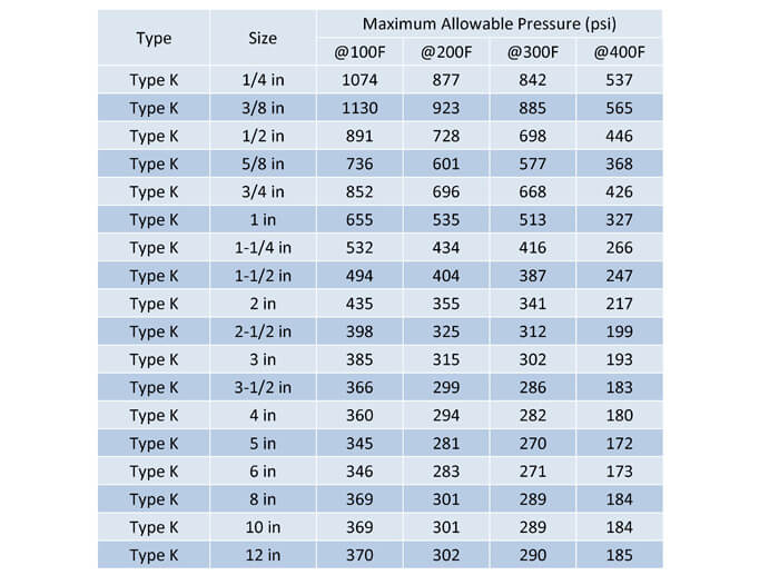
Table 18: Type K is the strongest copper pipe and thus has the highest allowable pressure. Although Type K piping is typically used for underground domestic water piping, you should also use this type when you have pressures exceeding 150 psi and larger pipe diameters.
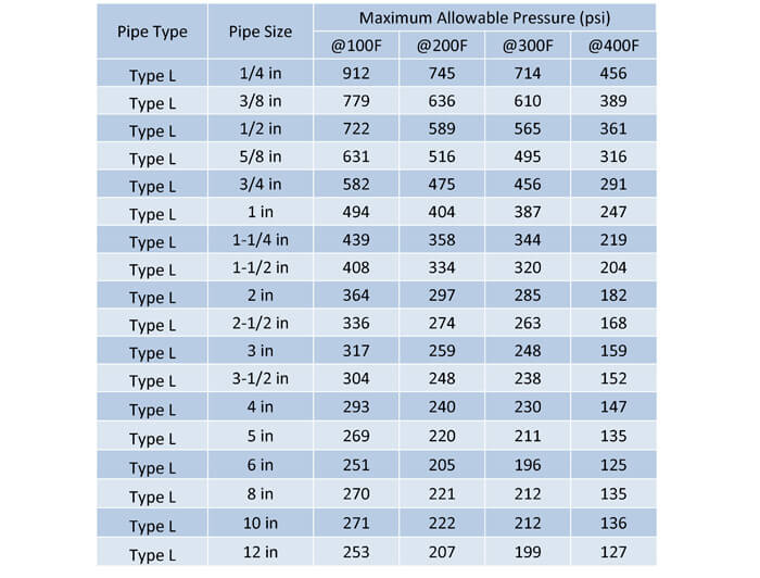
Table 19: Type L tubing is the 2nd strongest copper type. This pipe is typically used for indoor tubing and where pressures do not exceed 150 psi for larger tube diameters.
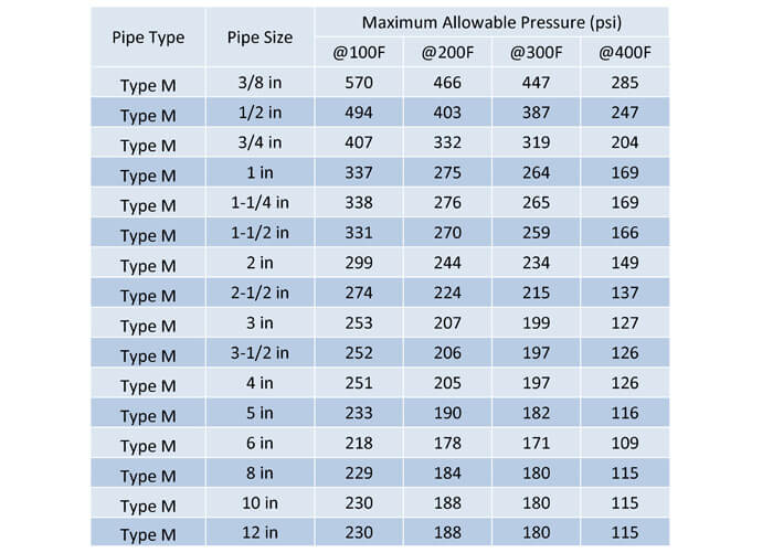
Table 20: Type M is the weakest of the three copper pipe types and should be used very carefully.
6.5 PEX PLASTIC PIPE AND TUBING
Cross-Linked Polyethylene or PEX piping’s main advantage is a plastic, polyethylene pipe or tube. This material is flexible, which means that the installation cost is lower than other piping. Crosslinking is a chemical reaction that links one polyethylene polymer chain to another. There are three main classifications of PEX piping, PEX-a, PEX-b and PEX-c. The different classifications describe the method of crosslinking. Each method meets ASTM F 876 and ASTM F 877, which determines the dimensions, pressure ratings and temperature ratings. However, the cost of each type is slightly different and the flexibility of each type is different.
The other classification of PEX pipes is whether or not the pipe has a barrier. Typically domestic water systems use non-barrier type PEX piping. The barrier refers to a laminated surface that is placed on the outside of the pipe, which restricts oxygen from entering the fluid. This is used for hydronic systems and other non-potable water systems.
Lastly, PEX cannot be used outdoors because it cannot withstand UV rays, unless it has a UV coating. Designers do not like to risk a pipe’s life on a coating, so PEX will not be used outdoors, similar to other plastic piping.
ASTM F 876 is the standard that specifies the material properties and the dimensions for PEX tube. ASTM F 877 is the standard that specifies the performance requirements for a PEX system, tube and fittings together. PEX tube is typically manufactured according to SDR-9. The dimensions for PEX SDR-9 are shown in the below table. The manufacturing method does not matter for the dimensions, since PEX-a, b, c are all manufactured to the same dimensions.
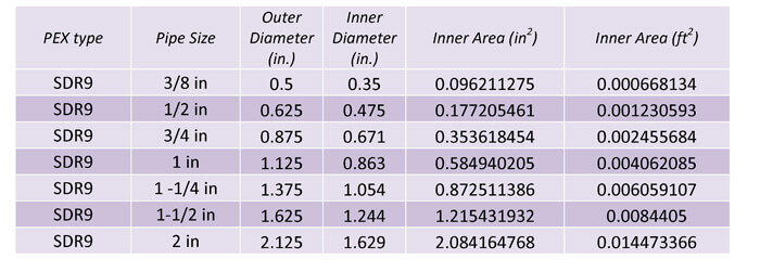
Table 21: This table shows the dimensions for PEX SDR-9 piping.
PEX piping is only used for smaller distribution pipes, up to 1” but some manufacturers do provide piping up to 2”.
6.5.1 PRESSURE RATINGS
PEX tubing typically has a maximum allowable water pressure of 160 PSI at 73 F, 100 psi at 180 F and 80 PSI at 200 F.
6.6 DUCTILE IRON WATER PIPE
Ductile iron is typically used by civil engineers as underground main piping. This pipe is not normally used by mechanical engineers for the building domestic water piping. This piping is suitable for underground, larger pipes because of its very long life. The piping is designed to last typically more than 100 years. The pipe is very strong and durable, so it can also withstand pressure loadings from being under roads and also any possible damage during handling and installation. Ductile iron is stronger than carbon steel piping and is also easier to work with, hence the name, ductile.
Ductile iron is an iron, so it is susceptible to corrosion. Linings are usually provided to slow down corrosion, but this will add cost to the piping. Ductile iron is relatively more expensive than its plastic counterparts.
Ductile Iron has different pressure classes. These classes identify the allowable water pressure. These classes include, 350 PSI, 300 PSI, 250 PSI, 200 PSI and 150 PSI. The outer diameters for each of the classes are the same, but the inner diameters are adjusted as the thickness changes for each pipe class. The higher pipe classes have increased thickness and smaller inner diameters.
The dimensions for these pipe classes are shown in the Domestic Water calculator.
6.7 GALVANIZED STEEL PIPING
Galvanized steel piping is in some cases an approved potable water piping but it is difficult to work with and subject to rust, which can cause leaks, decreased pressure and reduced flow.
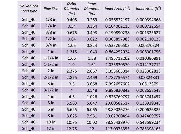
Table 22: This table shows the dimensions of galvanized steel, schedule 40 pipes.
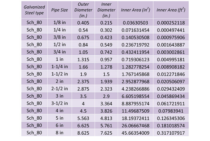
Table 23: This table shows the dimensions of galvanized steel, schedule 80 pipes.
6.7.1 PRESSURE RATINGS
The pressure rating for galvanized steel pipes vary based on the pipe size and schedule. The thicker schedules have higher pressure ratings and so do the smaller pipes. The maximum allowable pressure ranges from 2,000 psi for small pipes down to 200 psi for larger pipes and lower schedules. The pressure ratings are suitable for temperatures ranging from 0 F to 300 F.
6.8 POLYETHYLENE AND POLYPROPYLENE PLASTIC PIPING AND TUBING
Polyethylene and polypropylene are types of thermoplastic materials. These materials are not used as often for domestic water systems. These materials are typically used for fluids that are not chemically compatible with metal pipes. In addition, these materials can be used when corrosion is a concern, since plastic piping does not corrode. Plastic piping is also used because it is much cheaper and easier to work with than metal pipes.
However, these plastics are not as long lasting as their metal counterparts and do not do well when exposed to UV, unless the plastic has a UV coating. Some polyethylene pipe can be constructed with UV resistance built-in. In addition, plastic piping expands/contracts more drastically with changes in temperature and also has a much lower pressure rating than metal piping, especially at high temperatures.
Polyethylene (PE) and Polypropylene (PP) piping can range from sizes ½” to 65” but the calculator only includes the smaller pipe sizes since these are the most common for domestic water systems.
There are different types of PE and PP materials. These different types are usually given a four digit material code. The first two digits classify the cell, which determines the material’s density, tensile strength, slow growth crack resistance and much more. The second two digits determine the recommended standard hydrostatic design stress category. This is the basis used to determine the long-term strength of the pipe.
The applicable standards for polyethylene and polypropylene piping are (1) ASTM D 2239, (2) AWWA C901 and ASTM D 2737. ASTM D 2239 is titled the Standard Specification for Polyethylene (PE) Plastic Pipe (SIDR-PR) Based on Controlled inside Diameter. AWWA C901 is titled Polyethylene (PE) Pressure Pipe and Tubing, ½ inch through 3 inch for Water Service. AWWA stands for the American Water Works Association. ASTM D 2737 is titled the Standard Specification for Polyethylene (PE) Plastic Tubing. ASTM F 2389 is titled the Standard Specification for Pressure-rated Polypropylene (PP) Piping Systems.
6.8.1 PIPE DIMENSIONS
There are two ways that the pipe dimensions can be expressed for these plastic pipes, (1) SIDR and (2) SDR. SDR or standard diameter ratio was previously discussed with ABS and CPVC piping. SIDR stands for standard inner diameter ratio, which is the ratio of the inner diameter to the pipe thickness. SIDR is used for smaller pipes and for a special joining method that uses insert fittings. Thus the outside diameter can be varying, but the pipes can be joined as long as their inner diameters are the same.
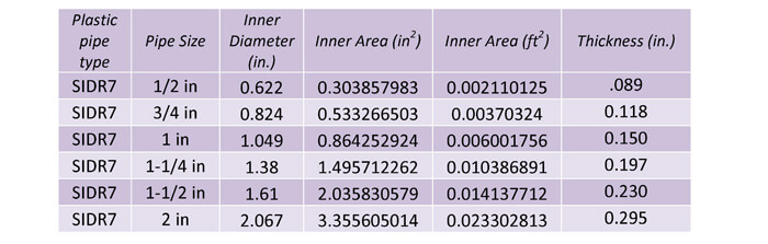
Table 24: This table shows the pipe dimensions for plastic SIDR7 piping. A lower number indicates a greater pipe thickness.
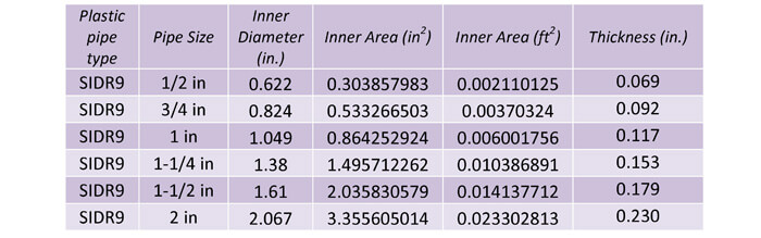
Table 25: This table shows the pipe dimensions for plastic SIDR9 piping. The higher number indicates a smaller pipe thickness. As you can see, the inner diameter is the same as SIDR7, but the thickness is smaller.
The second method that the plastic pipe dimensions can be shown is through the SDR or DR method. In this method, the outer diameters are the same and the inner diameters vary.
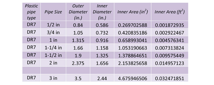
Table 26: This table shows the plastic DR7 pipe dimensions.
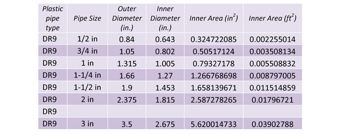
Table 27: This table shows the plastic DR9 pipe dimensions.
The calculator also has the following plastic pipe types, DR11, DR13.5, SIDR11.5, SIDR15, and SIDR19. The calculator only includes smaller pipe sizes for these plastics, because these are the sizes that are most common for domestic water systems.
6.8.2 PRESSURE RATINGS
The pressure ratings for plastic piping are much lower than metal piping. The pressure ratings range from 160 psi to 63 psi for the various pipe types. Also these pressure ratings are only for 73 F and the pressure ratings will drop as the temperature increases.
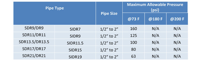
Table 28: Maximum allowable pressure for plastic piping
There are different material types within the overall PE and PP piping categories and each sub-material type will have slightly different maximum allowable pressures. So be sure to use these pressure ratings only as a guide and to check with the pipe manufacturer for the exact pressure ratings, based on the pipe temperature, pipe size, pipe type and sub-material type.
6.9 POLYVINYL CHLORIDE (PVC) PIPING
PVC piping is typically used for drainage, waste and vent systems and irrigation systems. PVC piping can be exposed to UV rays unlike most other plastic piping. This piping is cheaper, lighter and easier to join, compared to metal piping.
The applicable standards are (1) ASTM D 1785 and (2) ASTM D 2241. ASTM D 1785 is titled Standard Specification for Polyvinyl Chloride (PVC) Plastic Pipe, Schedules 40, 80, and 120. ASTM D 2241 is titled Standard Specification for Polyvinyl Chloride (PVC) Pressure-Rated Pipe (SDR Series). These standards govern the dimensions shown in the next section.
There are different types of PVC piping, PVC 1120, 1220, 2120, 2116, 2112 and 2110. These different types of PVC have slightly different material properties like density, strength, slow growth crack propagation, etc. Each sub-material type will have slightly different pressure ratings, but the dimensions will be the same for each sub-material type.
6.9.1 PIPE DIMENSIONS
There are two ways that the pipe dimensions can be expressed for these PVC pipes, (1) SDR and (2) Schedule.
The main SDR types are SDR 17, 21, 26 and 32.5. The lower SDR values have larger thicknesses and larger pressure ratings.
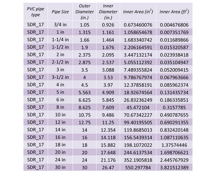
Table 29: This table shows the dimensions of PVC SDR 17 piping.
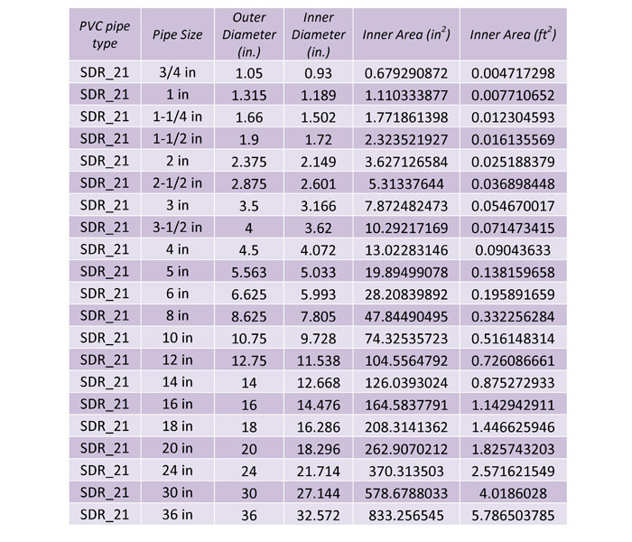
Table 30: This table shows the dimensions of PVC SDR 21 piping. SDR 21 piping has a smaller inner diameter
The calculator also includes SDR 26 and SDR 32.5. The two main schedule types are Schedule 40 and Schedule 80. Schedule 10 and 120 piping is also available but these are less common and are not included in the calculator.
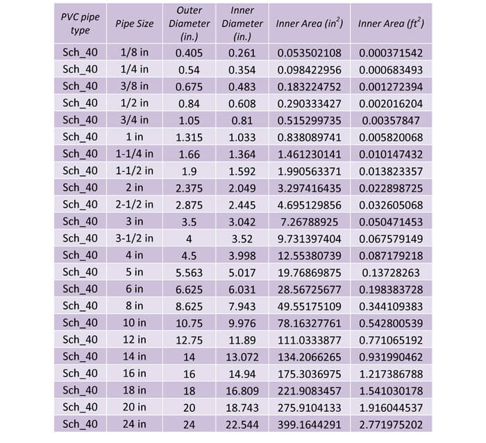
Table 31: This table shows the dimensions of PVC Schedule 40 piping.
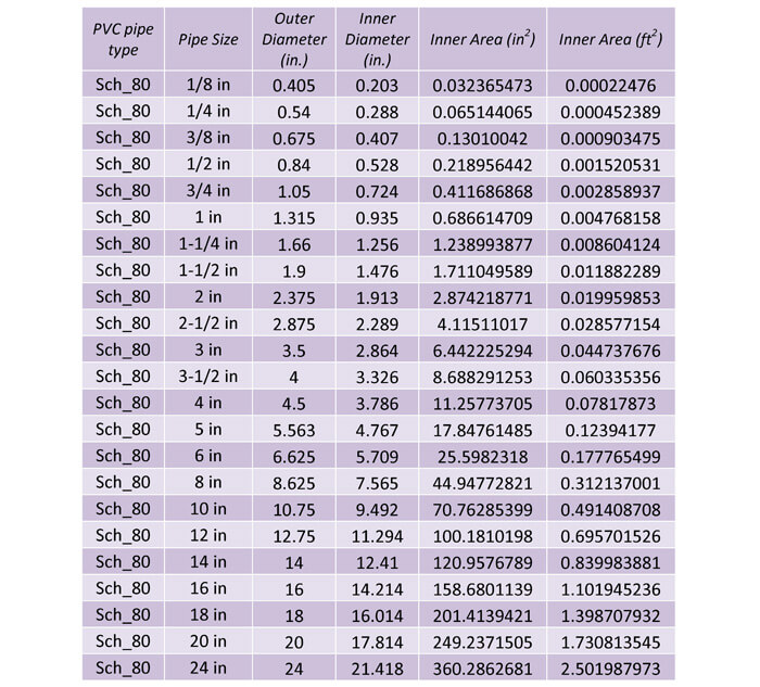
Table 32: This table shows the dimensions of PVC Schedule 80 piping.
6.9.2 PRESSURE RATINGS
The various PVC sub-material types and SDR’s has pressure ratings from 50 to 315 psi. The lower SDR’s have higher pressure ratings and the higher SDR’s have lower pressure ratings. Schedule 40 piping has a pressure range from 810 psi down to 60 psi, depending on PVC sub-material type and pipe size. The smaller pipe sizes have greater pressure ratings. Schedule 80 piping has a pressure range from 1,230 psi down to 60 psi, depending on PVC sub-material type and pipe size.
As the temperature increases, the pressure rating also decreases. The pressure rating decreases by nearly 22% when the temperature is increased from 73 F to 140 F. There are different sub-material types within the overall PVC piping material category and each sub-material type will have slightly different maximum allowable pressures. So be sure to use these pressure ratings only as a guide and to check with the pipe manufacturer for the exact pressure ratings, based on the pipe temperature, pipe size, pipe type and sub-material type.
6.10 STAINLESS STEEL PIPING
Stainless steel piping is not often used for domestic water systems due to its cost. Stainless steel is suitable for conditions where corrosion resistance is required. Although the name stainless implies that the pipe will not corrode, but it only means that the pipe is more resilient than other metals. The key to its corrosion resiliency is the chromium. Stainless steel is a steel alloy that is comprised of at least 10.5% chromium. A steel alloy is the combination of iron and another element, in this case chromium.
There are two main types of stainless steel piping and they are 304 and 316 stainless steel. The difference between 304 and 316 is the chemical composition. 304-stainless steel contains iron and (10.5%) chromium. 316-stainless steel contains iron, (10.5%) chromium and (2-3%) molybdenum.
There is another distinction added for stainless steels. A stainless steel will have other elements besides iron and chromium. For example, this is the typical composition of 304-stainless steel.
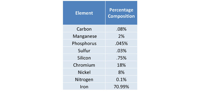
Table 33: The percent composition of typical 304 stainless steel.
A stainless steel can be distinguished with an “L” at the end of its number designation. This indicates that the stainless steel has a carbon percentage that is less than .04%. This low level of carbon increases the metals corrosion resistance. 304 or 316 stainless steel is more likely to corrode at weld locations, but 304L or 316L will have more corrosion resistance at weld locations.
In summary there are four main types of stainless steel pipe materials, (1) 304, (2) 304L, (3) 316 and (4) 316L. These materials are excellent for locations where corrosion is a concern.
6.10.1 PIPE DIMENSIONS
The pipe dimensions are the same for 304 and 316-stainless steel. The pipe dimensions only change with the various pipe sizes and schedules. ASTM A312 is titled Standard Specification for Seamless, Welded, and Heavily Cold Worked Austenitic Stainless Steel Pipes. This specification shows the outer diameters and the thicknesses required to meet the various schedules, 10S, 40S and 80S. Schedule 10S is the thinnest pipe and 80S is the thickest pipe. The outer diameters are the same for each schedule, but the thicknesses vary. Constant outer diameters allow pipes of different schedules to be connected to each other.
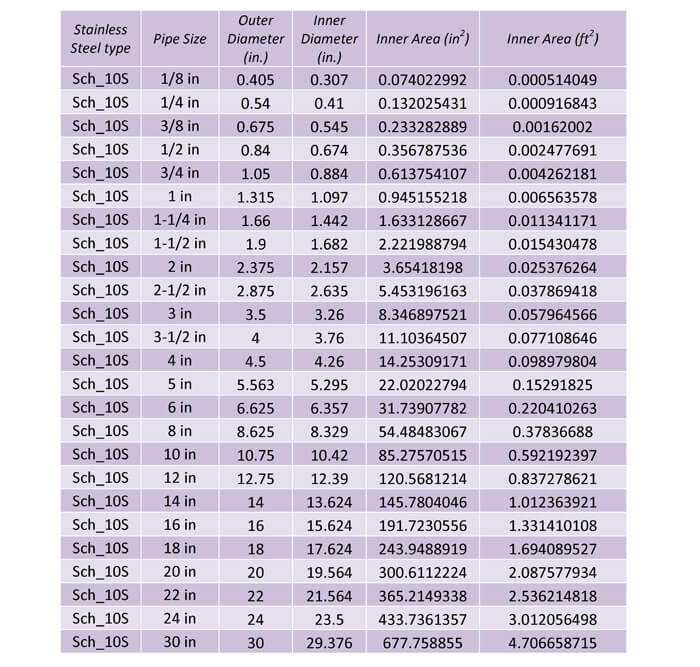
Table 34: This table shows the dimensions for schedule 10s stainless steel piping
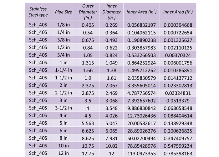
Table 35: This table shows the dimensions for schedule 40s stainless steel piping.
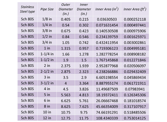
Table 36: This table shows the dimensions for schedule 80s stainless steel piping.
6.10.2 PRESSURE RATINGS
Stainless steel pipes have pressure ratings that vary based on the type, pipe size and schedule. The thicker schedules have higher pressure ratings and so do the smaller pipes. Similar to the other previously discussed metal piping, stainless steel piping has a maximum allowable pressure ranging from 2,000 psi for small pipes down to 200 psi for larger pipes and lower schedules. The pressure ratings are suitable for temperatures ranging from 0 F to 300 F. The 304 pipes will be stronger, since it has more iron and the 316 will be weaker.
7.0 VALVES
A valve is a pipe fitting that regulates the flow of a fluid. There are many types of valves, like the globe valve, plug valve, angled valve, butterfly valve and 3-way valve. As an engineer you should understand each type of valve and when to use each type of valve. The different names of valves are given based on the shape of the valve. A good resource for valves is at any valve manufacturer’s websites, like Cla-Val, Apollo Valves and Powell Valves. However another good source is at the control valve webpage at Emerson Process’s website.
7.1 TYPES OF VALVES
Globe Valve: A glove valve consists of a plug and a seat. The plug is raised and lowered to increase and decrease flow through the valve. Since the fluid has to make two 90 degree turns the pressure drop is much higher than other valves and the wear on the valve is greater.
This valve is characterized by infrequent operation, good flow control, high pressure drop and high pressure rating.
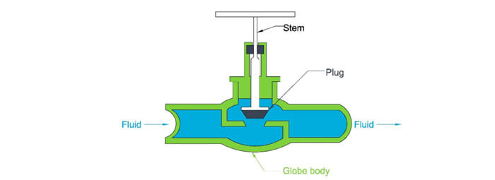
Figure 17: A section view of a globe valve. As the valve is closed, the plug is lowered into the seat, which blocks the fluid flow from moving up and to the right of the valve.
Ball Valve: A ball valve is called a ball valve due to the ball shape in the center of the valve. This ball has an opening on sides 180 degrees opposite of each other. The rest of the valve is solid. When the valve is aligned such that the openings are in line with the fluid flow, then the valve is 100% open. When the valve is aligned such that the openings are perpendicular to the fluid flow, then it is 100% closed.
This valve is characterized by frequent operation, bad flow control, low pressure drop and higher pressure rating. This valve can be used for on/off control but can also be used to regulate flow. The ball valve is the most common types of valve used in domestic water system. They are used as shut off valves to isolate parts of a building, in case maintenance is required in one area, the whole system does not need to be drained.
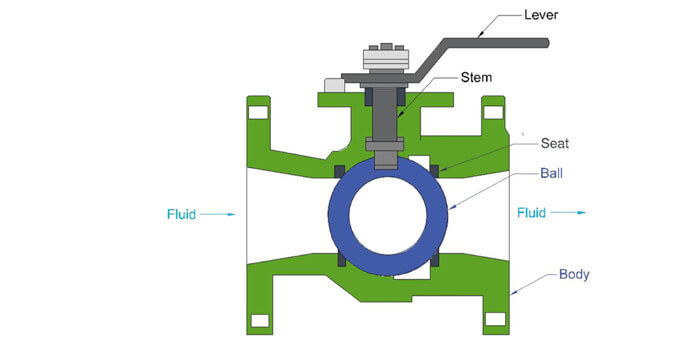
Figure 18: A section view of a ball valve. As the valve is closed, the plug is lowered into the seat, which blocks the fluid flow from moving up and to the right of the valve.
Butterfly Valve: A butterfly valve has a disc in the center of the valve. The disc is connected to a rod, which can be spun to open and close the valve. Rotating the rod turns the plate parallel or perpendicular to flow and any angle in between. Because the plate is always located in the flow, there is an increased pressure drop.
This valve is characterized by infrequent operation, bad flow control, low pressure drop and a low pressure rating.
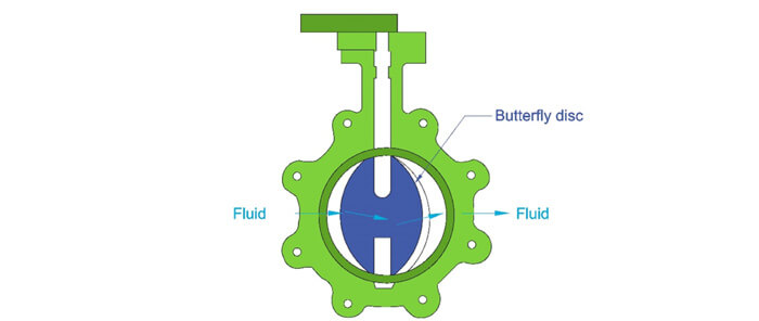
Figure 19: A section view of a butterfly valve. The valve is currently shown as a ¼ open. The fluid passes around the disc. As the valve is closed, the disc is perpendicular to the path of the fluid flow, creating a wall. When the valve is 100% open, the disc is parallel to the fluid flow.
Check Valve: This valve allows fluid to only flow in one direction. There are many different types of check valves. The most common are swing and lift check valves.
Gate Valve: A gate valve is used for on/off control and operates by lifting a gate out of the path of the fluid.
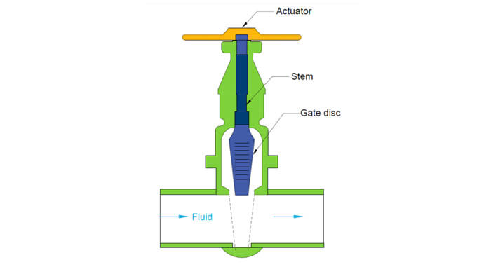
Figure 20: A section view of a gate valve. As the valve is closed, the gate is lowered into the seat, which blocks the fluid flow from moving from through the valve.
This valve is characterized by infrequent operation, bad flow control, low pressure drop and lower pressure rating.
Needle Valve: A needle valve has a similar build to a globe valve but instead of a disc there is a needle-shaped plunger that fits into the seat. It is primarily used for low flow.
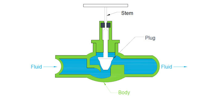
Figure 21: A needle valve has the same construction as a globe valve, except the plug is shaped as a needle as opposed to a disc. This allows for greater flow control, but also increased pressure losses.
This valve is characterized by infrequent operation, excellent flow control, high pressure drop and higher pressure rating.
7.2 VALVE FLOW CHARACTERISTICS
Flow characteristics describe the relationship of the flow rate and the % open/close status of the valve. For example, if a valve is 50% open, then the flow is at 50 GPM or if a valve is 75% open, then the flow is 80 GPM. This is an example of the term flow characteristics and a collection of these points’ results in a flow characteristics graph.
The graph shown on the following page is an example of a flow characteristics graph of various control valves. Each valve produced by a manufacturer will have a corresponding graph. This graph will allow you to properly select the type of valve that you need for your application. For exam purposes, you should be able to understand this graph and determine how the flow will be controlled by the control valve under various operating points.
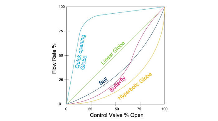
Figure 22: The flow characteristics graph gives the operating conditions of a control valve at a constant pressure.
As you can see from the above graph, there are a variety of different control valves, each with its own flow characteristics. The simplest control valve is the valve with linear characteristics, this means that if the valve is 50% open, then the flow rate is 50% and if the valve is 75% open, then the flow rate is 75%. The quick opening valves let through the majority of the flow when the valve is only slightly opened. The others need a larger percent opening to increase the flow.
If you needed tight control in a certain area near the 90% to 100% operating region, then you could use quick acting valve. If you needed tighter control in the 25 to 50% region, then the hyperbolic globe valve could be used. As an engineer you should be able to read these graphs and select a control valve that best suits your need.
7.3 VALVE SIZING METHOD
The sizing of a liquid valve is dependent on the following equation. This equation shows that for flow through an orifice like a control valve, that the square of the fluid velocity is directly proportional to the pressure drop across the orifice.
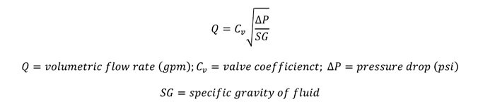
The valve is coefficient is specific to each valve and is found through controlled experiments. This value corresponds to the flow rate through the valve in one minute, when a pressure drop of 1 PSI is maintained across the valve.
8.0 Miscellaneous Design Issues
8.1 HYDRAULIC SHOCK OR WATER HAMMER
Hydraulic shock is the term used to describe the pounding noise and vibrations in a piping system when a volume of liquid flowing is abruptly stopped. A pressure wave is started at the point of fluid stoppage and is reflected back and forth from this point to a point downstream. This wave is slowly dissipated after a period of time. Devices in a domestic water system that can trigger water hammer include, solenoid valves, quarter turn valves (assumed quick closure), and flush valves. In many cases a loud sound is present with water hammer, as if someone was hitting the pipe with a hammer, hence water hammer. The sound may be upsetting to a client, but the cause of the sound is even more of a worry.
8.2 STERILIZATION OF DOMESTIC WATER PIPING
For all new and renovation work, the water system should be cleaned and disinfected. Disinfection is usually conducted with chlorine. It is injected into the system through a service cock, near the entrance into the building. Once the disinfectant is injected into the system at the correct concentration, it is then held in the system for a set period of time. After the retention, the concentrations are checked and if they are satisfactory, the system is flushed. Finally samples are taken at the furthest fixture and tested. An acceptable test shall show the absence of coliform organisms and should be submitted to the owner prior to the contractor permitting the use of any portion of the domestic water system.
8.3 WATER LEAK TESTING
This test is conducted prior to the sterilization of the system. It consists of capping all system openings and filling the system with water, and pumping a static head into the system at around 100 psi for at least 2 hours.


/GettyImages-497474893-56ca01395f9b5879cc4a95e6.jpg)


/cdn.vox-cdn.com/uploads/chorus_image/image/67842058/58c6edf2843a8bef7718bdf6_tom_silva_2.0.jpg)